Tuned Input
Jack W8BFS gives us good insight on the reasons why the TL-922 input tuned circuits need tweaking and he explains his methodology.
The symptoms:
“When an Anan 100B was first used at my station, the SWR to the TL-922A input was too high on certain bands and caused the output power of the 100B to reduce. Other radios had a higher SWR also, but still seemed to put out full power or close to it. Examining the SWR for the various radios versus the band used was confusing, as one radio would have a good SWR on a certain band and another not.
What the heck was going on?”
Test results:
“Changing the length of the Anan coax produced large changes in SWR on various bands. A Heathkit SB200 was substituted for the TL-922A and suddenly all issues were gone. Coax length didn’t matter, and all radios had a good SWR on all bands.
One TL-922 web site I found indicated that you should operate your radio with a 2 meter length of coax to the TL-922A input. What??? Something was definitely wrong with the TL-922A and needed to be fixed.”
Solution:
“The culprit is a design flaw with the Q of the tuned input circuits. It is too low for the 160 through 20 meter bands. Comparing the schematic of the SB-220 and L4B tuned input capacitor values revealed that the TL-922A capacitor values were about half of what they should be.”
Testing a solution to work:
“The 80 meter band was selected to test and verify that this indeed was the problem. An inductance meter was used to determine how many turns of wire needed to be removed from the Kenwood 80 meter tuned input coil with the adjustment core at the halfway point. The coil was reinstalled in the amplifier with temporary compression trimmer capacitors to determine the optimum capacitance for both capacitors on either side of the coil. Results were very encouraging, and all radios now had SWR values of 1.3:1 or less at the band edges, and 1.0:1 SWR at the band center. As hoped for changing the coax length now has no effect!”
Full Implementation:
“Changes were made to all of the tuned input circuits. The capacitor combination values shown below are suggested. You can use different combinations to get the desired capacitance. The tuned input circuit changes follow:
160 Meters: Change C49-1000 & C50-560 to 1700 total with a 1500 & 200. Change C47-560 & C48-1000 to 2000 total. Remove 5 turns from 160 L9 coil resulting in 22.5 turns. (10uh to 6.3uh) Tune L9 for lowest SWR at 1900. Q is 1.02.
80 Meters: Change C52-330 & C59-220 to 1377 total with a 1247 & 130. Change C51-330 & C57-220 to 1303 total with a 1247 & 56. Remove 4 turns from the 80 L10 coil resulting in 14.5 turns. (4uh to 2.3uh) Tune L10 for lowest SWR at 3750. Q is 1.7.
40 Meters: Change C54-470 to 1150 total with a 1000 & 150. Change C53-330 to 1120 total with a 560 & 560. Remove 3 turns from the 40 L11 coil resulting in 6.5 turns. (2.3uh to 1.05uh) Tune L11 for lowest SWR at 7150. Q is 2.6.
20 Meters: Change C56-220 to 225 total with 195 & 30. Change C55-150 to 100 total with a 100. Remove 1.5 turns from the 20 L12 coil. The last half turn is made by 45 degree angle of wire rather then perpendicular to the coil. (1.2uh to .62uh) Tune L12 for lowest SWR at 14175. Q is 1.
15 Meters: No change needed. Tune L13 for lowest SWR at 21225. Q is .8.
10 Meters: Change C60-120 to 90 total with a 47 & 43. Add 47 to output (tube cathode side). Tune L14 for lowest SWR at 28600. Q is .8.”
I implemented these changes and I found it a bit easier to do so by viewing the mod thinking about it as INPUT and OUTPUT sides of the band coil being modified. I will share this just in case you find it helpful. Full credit is to Jack W8BFS.
160 Meters:
Change C49 and C50 input side to 1700pf total (1500 + 200 perhaps)
C47 and C48 output side to 2000pf (2x 1000 perhaps)
Remove 5 turns from 160 L9 coil resulting in 22.5 turns. (10uh to 6.3uh)
Tune L9 for lowest SWR at 1.900 MHz. Q is 1.02.
80 Meters:
Change C52 and C59 input side to 1377pf (I used 1200+180pf)
Change C51 and C57 output side to 1303pf (I used 1300 and two 3pf by measuring the C)
Remove 4 turns from the 80 L10 coil resulting in 14.5 turns. (4uh to 2.3uh) Tune L10 for lowest SWR at 3.750 MHz Q is 1.7.
40 Meters:
Change C54 input side to 1150pf (I used 1000+150pf )
Change C53 output side to 1120pf (I used 2 x 560pf)
Remove 3 turns from the 40 L11 coil resulting in 6.5 turns. (2.3uh to 1.05uh) Tune L11 for lowest SWR at 7.150 MHz. Q is 2.6.
20 Meters:
Change C56 input side to 225pf (I used 180 + 47 pf)
Change C55 output side to 100pf (I used a 56 and a 47 pf measured 100)
Remove 1.5 turns from the 20 L12 coil. The last half turn is made by 45 degree angle of wire rather then perpendicular to the coil. (1.2uh to .62uh) Tune L12 for lowest SWR at 14.175 MHz. Q is 1.
15 Meters: No change needed. Tune L13 for lowest SWR at 21.225 MHz. Q is .8.
10 Meters:
Change C60 input side to 90pf (I used 47 & 43pf).
Add a 47pf cap to the output side
Tune L14 for lowest SWR at 28.600 MHz. Q is .8.
I purchased all my Silver mica caps from China using Ali Express. I just typed in “silver mica capacitor” and the supplier I purchased from was called AEAK. They had a really good range of values all rated at 500 volts. Due to tolerances and manufacturing variation it would be better to have a wider range to cherry pick to get the values right. I used a meter to measure values and this helped me get the correct values despite the tolerance variation.
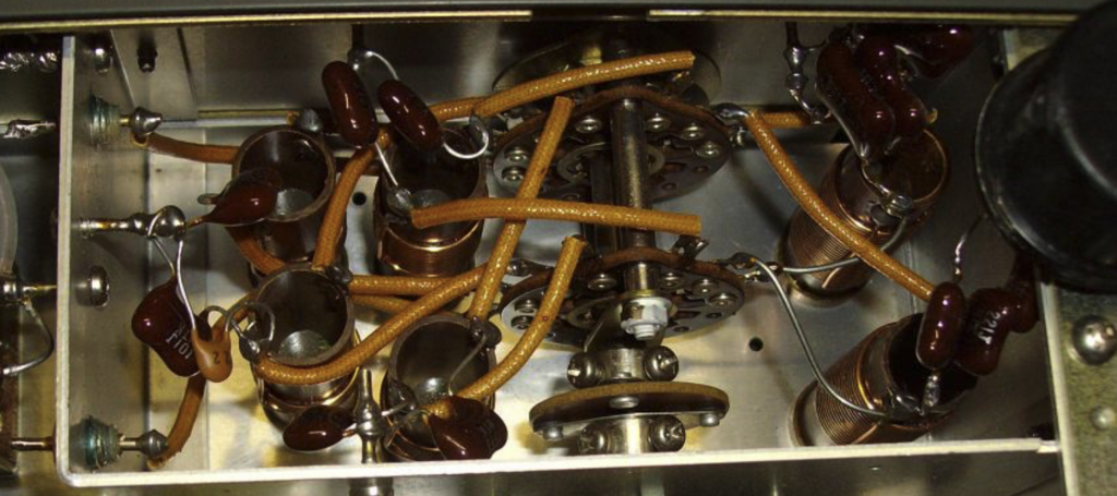
Image credit: F4EOH