Bias Adjustment
The original TL-922 used a 7.5 volt Zener and had no way to adjust the bias. Don Kessler sorted this in his kit. He provides a simple arrangement where you move a shorting link over a string of pins to select the optimum idle current. It is very neat and tidy. The kit is an easy install and his instructions are superb.
Just a safety note: Adjustment is never to be made while powered “ON”. The tubes must ALWAYS be vertical, base up or down but NEVER horizontal with the power on. Even if it is just the filaments.
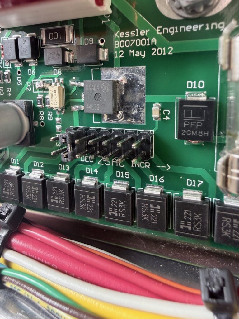
Across the bottom of the control PCB you will see diodes D11 to D18. Above the string of diodes are the 2 pin headers. You can see a 2 pin shorting lug is covering the pair 2nd from the left.
The “ZSAC” under the jumpers stands for “Zero Signal Anode Current” The closer to the left that the jumper sits, the lower the idling current. As you move the jumper to the right the idle current increases. You have 8 possible set points in this string. No jumper at all, is option 1. Then you can jumper or bypass D11 first and progress right bypassing them cumulatively. REMEMBER. Do not adjust with the amp on its side like this while powered up.
Here is another view of the control board installed.
In case you are interested, the 2 pin connector on the bottom left is for the Step-Start. The 5 pin connector, slightly to the right along the bottom edge is the connector to the front panel and drives the “On Air” and “Standby” LED’s as well as four LED’s for the illumination of the meters rather than the original incandescent bulbs.
The 10 pin header is the 8 VAC and the 80 VAC power from the other filament transformer windings. It also receives the PTT signal from the transceiver. Not only is it fully compatible with modern transceivers, it is also fast for QSK operation if required. The control board also delivers aerial change over relay power, and feeds the grid bias voltage for the tubes.
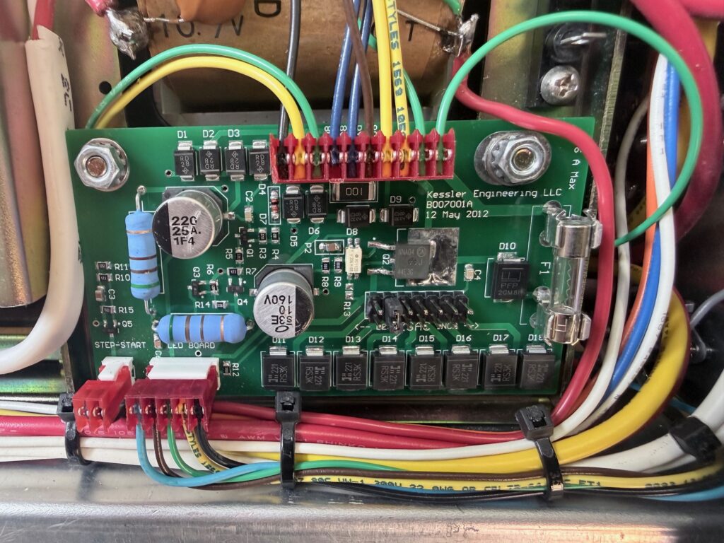
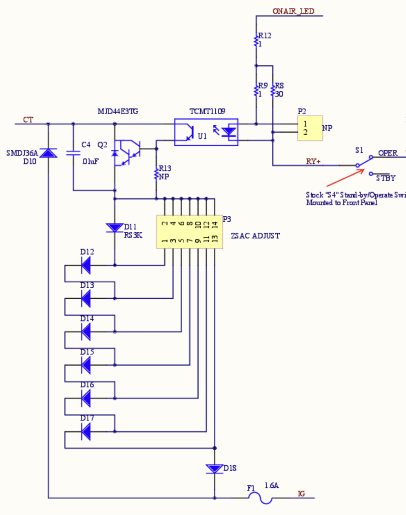
Image credits: Kessler Engineering and VK3BBQ