Kessler Engineering Kit
Multi-Item Kit
Kessler Engineering have made an outstanding kit for the TL-922. I am very happy with the results. The install was not difficult. What to expect in the kit if you decide to go that way.
- Step-Start In-Rush Current Protection
- Low Voltage PTT Switching for use with modern solid state transceivers
- Quieter T/R switching
- QSK Operation
- Electronic Bias Control
- LED “On-Air”, “Standby”, and Meter Illumination.
All of the above features come on four fully populated PCB’s. The kit includes wiring harness’s for all interconnections. Even any hardware required like nuts, washers, wire ties, etc etc. are all in the kit. The only thing we bring to the party is your TL-922, a soldering iron, a pair of eyes, your hands, and half a brain. The instructions are detailed, clear and precise. It’s that good!
By the way, I have no affiliation with Kessler Engineering other than being a happy customer.
The Kit
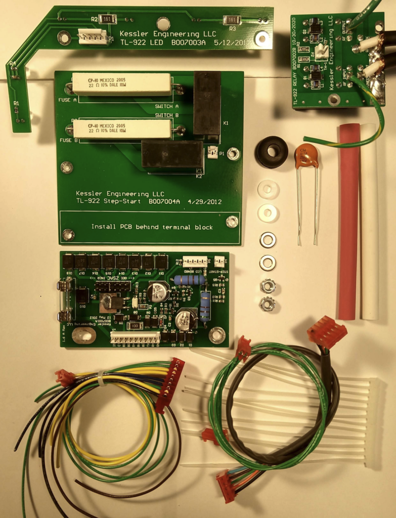
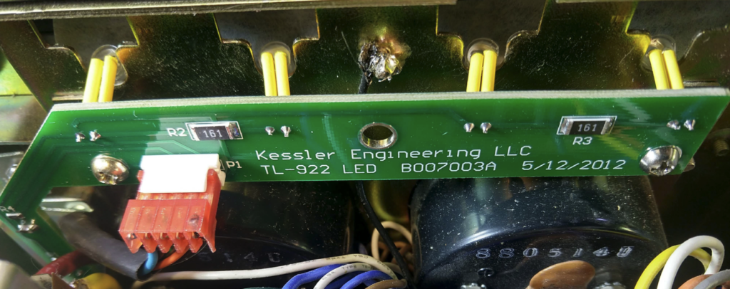
LED Replacement PCB
At the top LH side of the first picture is the Meter lamp replacement PCB with LED’s. The LED’s are facing down. Look closely at the LH dog leg of the PCB and you can see the sides of the two LEDs for “On-Air” and “Standby” lamps. Also just faintly visible, is a bit of reflected light underneath the lower edge of the larger section of the PCB. This is from the 4 LED’s used to illuminate the meters. The original bulbs would now be quite hard to obtain I suspect, if not impossible. Mine all still work but I changed out to the LED option that gets it sorted once and for all.
The image at right is the PCB in position with the four meter LED’s angled down over the meters.
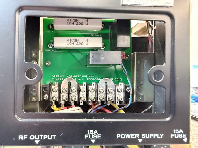
Step-Start Inrush protection
The next board down, is the Step-Start PCB that fits under the back fan cover.
The original 240 mains fuses remain. Each mains cable has its own 20 ohm 10 watt resistor and a relay to bypass the resistor after the delay. So it has 40 ohms in-circuit initially to accomplish the soft power-up. More detail of the soft start are referenced under the “More Mods” pull down and then select “Power Switch”
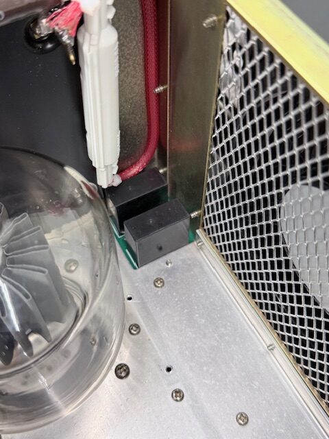
Antenna Change Over Relays.
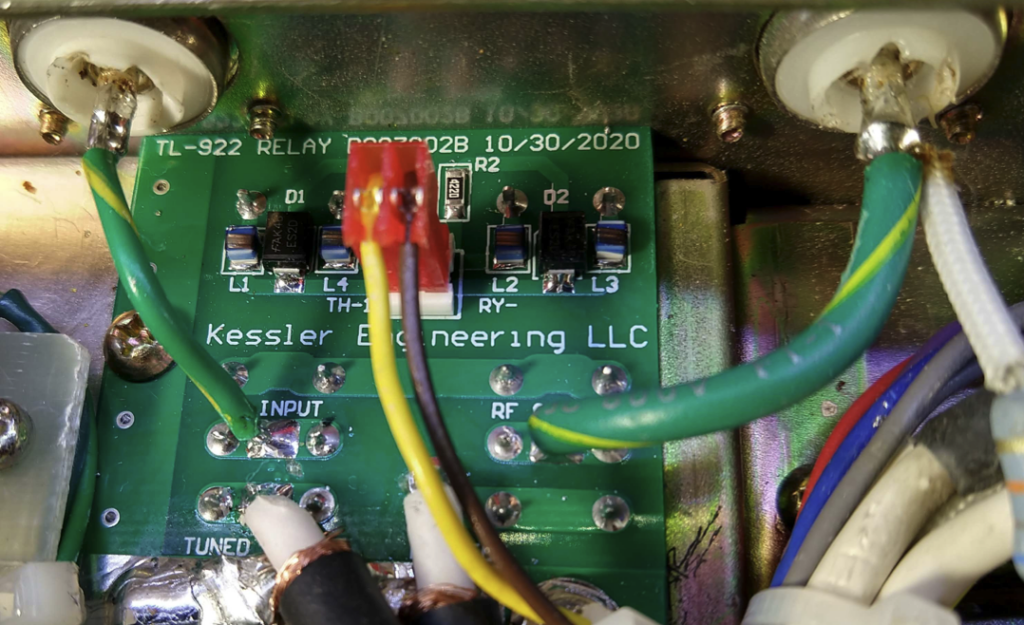
This view is from the under side of the amp. The location is where the original Bias relay was located. Early versions of the Kessler Kits used vacuum relays. Due to the ever increasing cost as well as the fact that vacuum relays are getting harder to find, they have re-engineered it using suitable normal relays with heavy duty contacts.
Top-side, it simply sits in the corner of the tank compartment. Please ignore the 5kV fuse holder and the RF shield in front of the fan. These are detailed elsewhere on the site.
The last PCB is the Control PCB
This brings everything together, it drives the LED PCB above. It controls the Step-Start as well as the aerial change over relay boards.
In addition, it now adds the low voltage control on the PTT line, so that modern transceivers work seamlessly. It also provides QSK operation with fast and quiet change over, and delivers Electronic Bias control with a simple adjustment method.
The control PCB mounts nicely using two existing transformer bolts. The 10 pin connector on the top of the PCB gets power for LV control circuits from the 8 VAC transformer winding, on a pair of blue wires. The Bias control voltage is derived from the 80 VAC winding feeding the board on the pair of yellow wires. The other wires from this connector pickup the PTT line, process it at safe logic levels, delivering it at QSK speeds and drives the aerial change over relays. In addition, it provides electronic bias adjustment by a simple jumper (8 possibles) for the finals.
The 2 pin connector in the bottom LH of the picture delivers the control of the Step-Start relays. The 5 pin connector drives the LED PCB as well as the “On-Air” and “Standby” LED’s.
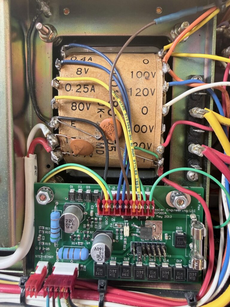
Image credits: Kessler Engineering and VK3BBQ