Filament Voltage
Filament voltage on a single 3-500 should be a nominal 5 volts, with ¼ volt tolerance either way. This is what the tube manufacturers specify.
Many years ago a ham with excellent writing skills and a way with words, penned an article that was published in QST. He indicated we could extend the life of our tubes and recommended we reduce the filament voltage. Another way of looking at this, he was saying we were prematurely killing our tubes by doing what the manufacturer recommended. To reduce the filament voltage you could buy a kit he sold. The kit used NiCh wire to do the voltage reduction. I admit it. I was sucked in and purchased the kit (and the NiCh parasitic suppressor kits, more on that later) I fitted the NiCh wires, and dropped the voltage as suggested.
Later I ripped it out because that was simply not true. Reduced voltage on the filaments was going to reduce tube life not extend it. What a disservice to the amateur fraternity.
The TL-922 has the ability to be either 110 volt or 230 volts powered with suitable jumper settings under a rear cover. In my case, being a 240 volt market, I decided that jumpers for 110 were of no value. I could not foresee me selling and shipping my amp to the US, ever. So I made some changes and no longer have the ability to easily change to 110 volt input. I have removed the label on the rear terminal cover so as not to mislead anyone who was looking at my amp thinking it was still standard and try moving the jumpers. This is a safety issue. If you choose to change the purpose of the terminal strips on the back of the amplifier you must remove the label that details the 120/240 jumper settings. You would never want to have someone imagining that they are still as per original and coming to harm for the sake of a sticky label.
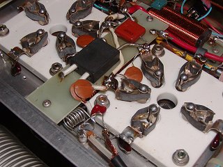
What is a really nice, in the TL-922, is the two transformers. The HV transformer is independent of the transformer for the filament and bias supply. This allowed me to reconfigure one of the terminal blocks under the back cover. I could set the filament transformer to a suitable primary tap that gave me the 10 volts secondary the filaments required. (2 x 5 V in series). I could also use a different tap on the HV transformer as the two transformers were no longer in parallel but independent. With the two transformer primaries now appearing separately on the terminal block and I could adjust them individually by moving the jumpers. I no longer have any simple way to change 110/240, but I will never need it. What I can do, is, easily adjust the filament voltage if required. As an example of the necessity; Imagine I changed QTH and the mains supply voltage was lower at 220 volts, or something like that. I can change the taps to bring the filaments up to the required voltage.
My mains voltage in the shack varies from 235 to 240 volts be it mains or my solar batteries via the Tesla inverter. So 2% variation means my filaments never go out of spec at this current QTH based on that level of mains variation.
Why I ever purchased the NiCh kit to lower filament voltage leaves me feeling like a bit of an idiot. The whole purpose of the filament is to make electrons readily available for use, either directly heated, or inside a cathode. Reducing voltage obviously means the cathode will run cooler and have less available electrons. If we keep the plate voltage high and want to draw peak current, we run the risk of ripping or tearing electrons off a cathode that is too cold, and unable to realise peak current. Today, it seems like madness that I ever thought that ignoring manufacturer specifications was a good idea.
I would like to thank Tom, W8JI for his in-depth review on the importance filament voltage plays. The following article covers the subject in great detail, and is not just confined to the 3-500’s used in the TL-922.
https://www.w8ji.com/filament_voltage_life.htm
Thanks for the great read, education; and for saving my 3-500’s.
Long live the finals!
Filament Arrangement
Honestly I do not know if this is advantageous or not. I do not have any technical reviews or performance test results to prove it one way or another. All I have is the logic behind it, and the fact that it costs nothing to implement and perhaps it might realise a fractional advantage.
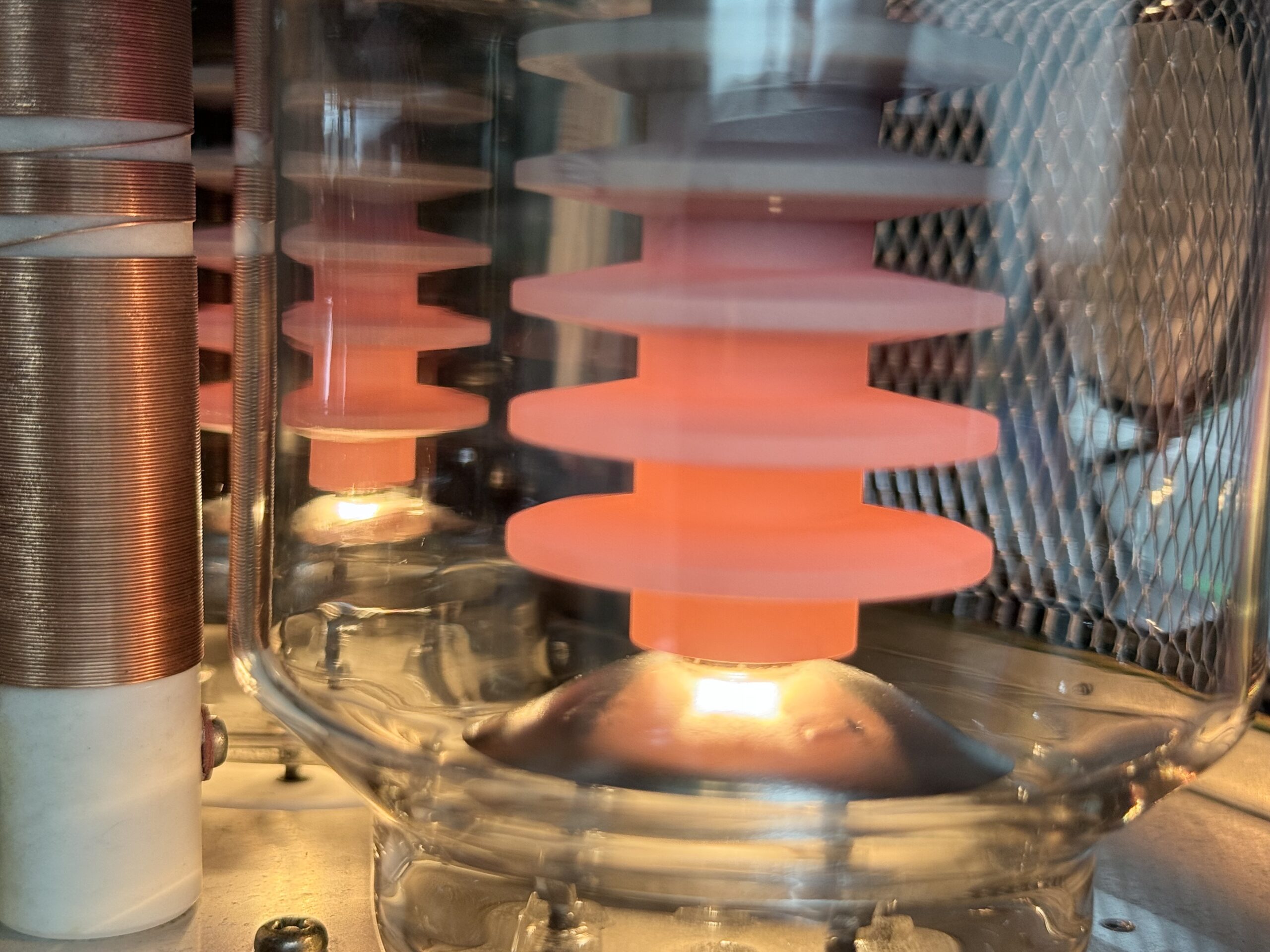
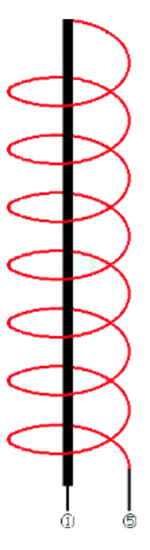
JH2CLV noted that the physical structure of a 3-500 filament is that Pin 1 is the central support structure of the filament. The actual heater element here is drawn as a spiral construction that drops to the bottom of the tube and then exits at it were, on Pin 5. Please see this image copied from JH2CLV’s web site. The photo of the actual filament is courtesy of w8ji.com.
In a stock standard TL-922 when in operation the drive is arriving on the first tube on Pin 1 and simultaneously on pin 5 of the 2nd tube. It’s as if they are not in sync or 180 degrees opposite. We could rearrange the wiring so that drive appears on pin 5 of both tubes simultaneously. In-sync or in-phase if you will.

It is not a difficult change. As mentioned, I have no idea if this makes any difference at all. At the end of the day it can’t hurt. So while undertaking modifications I decided to do it.
Image credits: VK3BBQ, JH2CLV and W8Ji.