Glitch Resistor – HV Fuse
Glitch Resistor
Glitch resistors help limit damaging currents in case of a catastrophic tube fault, like an Anode to Grid short. (perhaps due to a gassy tube)
AG6K, (SK) had published some comments about glitch resisters in amplifier design and it’s a good read.
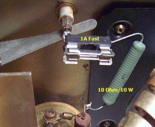
During a major problem, the anode (plate) current meter and other amplifier components can be subjected to a large current surge as the HV filter capacitors discharge. The peak discharge current can exceed 1000a if a series resistor is not used to limit the short circuit current that can be delivered by the HV filter capacitors. The current limiting resistor is placed in series with the positive output lead from the filter capacitors. A wire wound resistor with a high length to diameter ratio works best. A 10 ohm, 10W wire wound resistor is adequate for up to about 3kV & 1A. For higher voltages, additional 10 ohm, 10W resistors can be added in series to share the voltage drop during a glitch. Wire wound resistors with a high length-to-diameter ratio are best for this type of service.
Since about 1985, Eimac® has recommended the use of a glitch protection resistor in the anode supply circuit. Svetlana® typically recommends using a 10 to 25 ohm glitch resistor.
A HV current limiting/glitch resistor may disintegrate during a major glitch–so it should be given a wide berth with plenty of chassis clearance. If the chassis clearance is minimal, its a good idea to cover the chassis with electrical insulating tape.
Glass-coated (a.k.a. vitreous) wire wound resistors are the most suitable type of resistor for this application. If a glass-coated resistor comes apart during a major glitch, it won’t be throwing chunks of shrapnel around–like a less-expensive rectangular ceramic-cased resistor often does. Metal-case power resistors should not be used in this application. If a glass-coated glitch resistor is damaged during a glitch, it should be replaced with two such resistors in series to reduce the peak V-gradient per unit of length during a problem.
I used a pair of Ohmite B12J10R in series. These are each 12 watt 10 Ohm Vitreous Enamel units. They are rated to withstand 10 times the rated wattage for 5 seconds. That more than enough time to have the HV fuse kick-in.
Here are some photos of what others have done. You can judge for yourself how closely they adhere to the suggestions.
HT Fuse
Amateurs have used a wide variety of different fuse types to offer some protection.
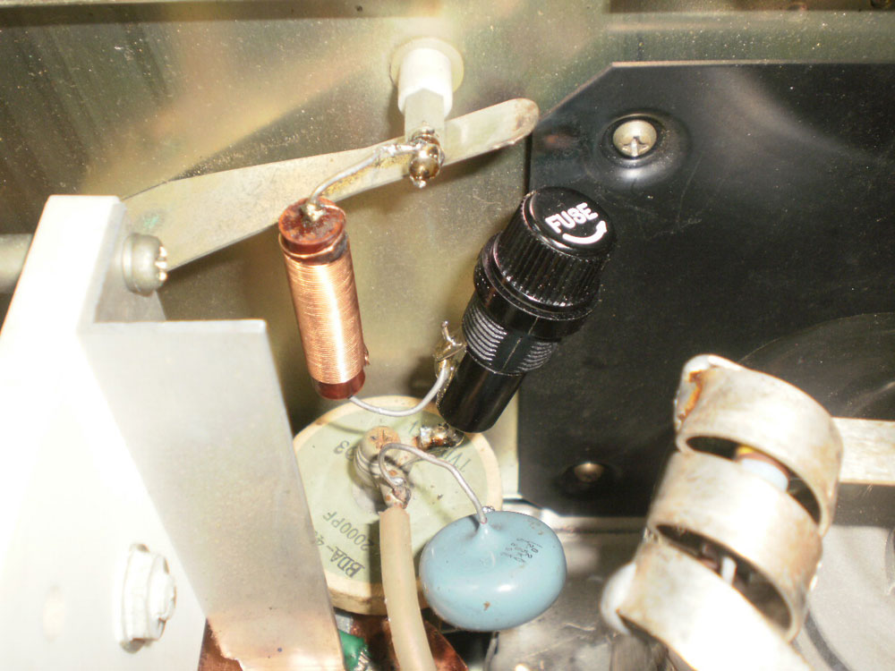
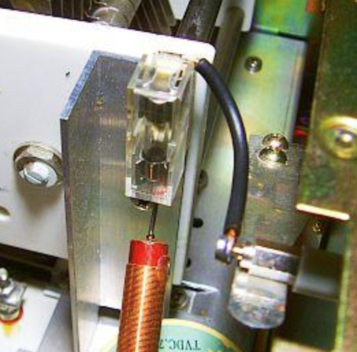
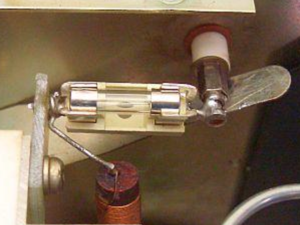
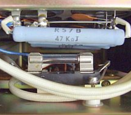
From a thin wire element in the HT line, to small 240 volt rated glass fuses, mounted in plug in receptors. I have even seen some use a panel mount fuse holder and support or hang it, internally.
Look closely at the picture, and you can see the very thin fuse wire between the ceramic post and the HV feed through.

The voltage rating of a fuse is typically a measure of reliable and effective circuit disconnection of the equipment up to the voltage rating. You can trust that it will open circuit when needed.
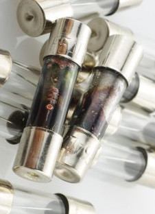
What might happen when we use a 250 volt rated fuse, at 3000 volts? Ever looked at a glass fuse and seen a silver/black metal coating on the inside of the blown fuse? That black coating is the metal of the fuse wire that vaporised in an explosive flash of heat, and coated the inside of the glass.
That metal coating at 3000 volts might still conduct, providing sufficient path for an arc to continue to run. Hence no circuit disconnection. A fuse rated at 250 volts might let us down badly.
If we perhaps used an open thin strand of wire as our fuse, and it popped, it might have coated nearby items with vaporised metal that is conductive. Not a great outcome. In the case of a glass fuse, we sometimes see that the glass exploded like a mini hand grenade. Hand grenades in the tank compartment. That too is a right mess to clean up.
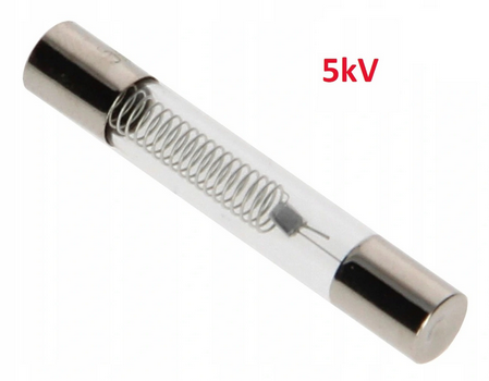
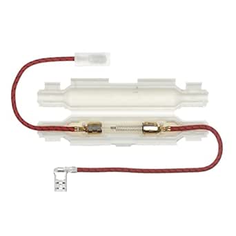
So what makes a high voltage fuse? Microwave ovens, have a 5kV rated HT fuse. Typically they are longer in length and have an internal spring that keeps the fuse wire taught. When the fuse pops, the spring retracts away from the break, creating a much wider air gap between ends. The fuses are available at reasonable cost from China’s Ali Express. The fuse can be purchased with a plastic protector or case that is 100mm long. If the glass decides to do its hand grenade trick, the shrapnel stays within the plastic housing and not all over the inside of your amplifier.
What fuse are you using?
What I did in my amplifier.

I used two small, 2 lug terminal strips that fitted under the two top mounting screws of the black heat shield in the tube compartment. These were perfectly spaced for the two Ohmite resisters in series

I ran a stainless threaded rod inside the two resistors to provide rigidity and used nylock nuts to hold them nicely.
In the 2nd photo, let’s start following the path from where the HT feed through comes into the RF compartment with its standard HT safety interlock. I used coax inner as the insulated HT conductor, and fitted a red polypropylene woven braid over the top of the coax core, just to add an extra layer of safety. The B+ then runs down through the 5 kV rated fuse in its plastic holder and then feeds the resistors from the left, and then connects to the standard RF choke. (wide angle lens’s are a bit distorting, but you get the idea)
Image credits:PA0FRI, WB8BFS, caradvise.com, AliExpress and VK3BBQ