Mods I don’t recommend
Single point ground on grids
Don’t follow advice to have a single point ground. We want as much stability as possible. In so many VHF and UHF tubes, the manufacturers got away from pins altogether and developed tubes and sockets that are coaxial in nature. This maximises RF performance. Keep the lengths as short as possible and using wider and larger surface area connections.
With the 3-500’s we are stuck with pins. Get the grids to ground by the most direct path possible, and use substantial surface area paths. True we are not at VHF and UHF, but don’t discard good design technique. Ask yourself, “What possible benefit is going to be achieved by ignoring RF fundamental design concepts?”
On the Home page, “Grid Grounding” is a top-line menu item. See what others have done. Evaluate the full range of pro’ and con’s and then, don’t be shy, “get them thar grids solidly grounded”.
Don’t add worms
You might have seen a recommendation to add a thin wire from the grids and directly attach it to the ground side of the plate tuning capacitor.
Don’t do this!
I had to laugh when I read a post where an RF Engineering guru who described his repair on a mates TL-922, to a de-worming treatment.
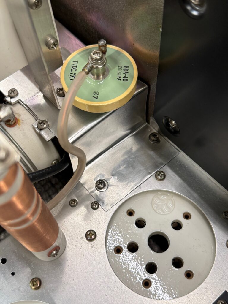
Here in the photo below, the copper strap joined the grids on both tubes and then they fed the white wire up to the ground side of the plate tuning capacitor.

Long thin wires at RF start to look more like inductors the higher you go in frequency. Please – don’t add worms. Instead copy what others have done using aluminium sheet or flashing. It will work so much better than infesting the amplifier with worms.
Worms can be found even in the input circuit
Another case where a long wire is presented as an enhancement. This time it is in the input tuning of the amplifier.
Please note: There is a page specifically about the input tuning. Look under the “More Mods” link on the home page then scroll down to the “Tuned Input” link.
The issue is that the TL-922 input tuning is not the best. It has been reported that operators have found that some transceivers would start to lower their output because the amplifiers input SWR was poor. Others found a work-around by fitting a 2m long coax or possibly another length between the rig and the amp, trying to get a better result.
The “Tuned Input” page will discuss a much better fix for this issue
The long wire (worm) enhancement logic was described this way. The writer is referencing all the tuned circuits from 160 to 10m in the input compartment.
“The circuits are in a Faraday cage and don’t allow the RF current to return to ground directly. You can put an insulated tinned copper wire through the hole of where a ground pin used to be and use this as a central grounding point (left). The best way to do this to ground all capacitors of the input filters on this earth wire. In the meantime this was only done for the 10, 15 and 80 meter input circuits.”

Look closely. He mentions that he has applied this to the 10 & 15 coils, (that’s the two coils on the LH side). Those two have their silver mica caps tied to his new long wire. The other is the 80m coil and that’s the bottom RH coil.
The long wire exits the compartment on the LH side through an insulated feed through, then takes a 90 degree turn and travels a further 1¼ inches to pick up a standard TL-922 earth pin. If all the remaining caps were swapped over to this long wire, as he recommended, then the path along the long wire to ground would be very much longer than the way they are all currently grounded. Look at how much shorter the standard configuration is. We keep coming back to good RF practice. Always keep the path to ground as short as possible. It is pure fallacy to say “The best way to do this to ground all capacitors of the input filters on this (long) earth wire.” The standard 10m coil only has 2.5 turns. The 5½ inch long wire is adding inductance in all the capacitor return lines to varying degrees across all bands. (depending on total path length to ground each band has). Does anyone think this long wire fixes all six bands simultaneously?
Worms are not good!
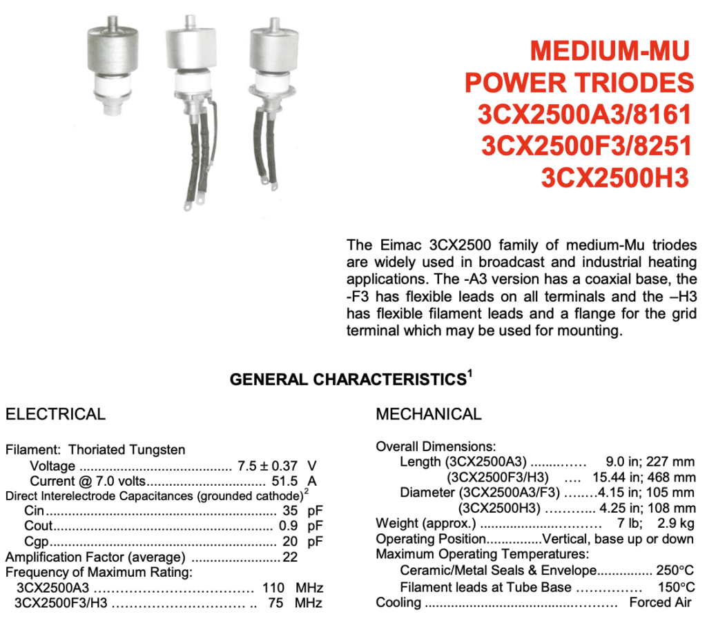
As an example of the difference it can make. Consider the data sheet for the 3CX2500A3 versus the same tube but the F3 and H3 variants. The variants have the long leads welded to the tube (ie worms added). I draw your attention to the bottom 2 entries in the left hand column of the data sheet. These are the maximum frequencies at full power. These worms just cost 35 MHz of top-end usable frequency performance at maximum ratings. Just 8 inches of filament/cathode leads were responsible for the the drop in performance. The data sheet tells no lies.
Do NOT reduce filament voltage below manufacturers spec.
Please check the review regarding filament voltage, under “Filaments”, a top line menu item from the home page.
On the Filaments page is also a link for an outstanding technical explanation by W8JI on filaments in general, not just the 3-500Z’s.
If you think lowering the voltage is going to extend the life of the finals. It won’t! It is a lie. If applied, you will reduce tube life.
Image credits: W8JI, VK3BBQ. PA0FRI and Richardson Electronics.