Grid Grounding
1st some history
Tom Rauch, W8JI provided some interesting background. The single biggest issue was introduced early on, when amplifier manufacturers tried to copy the design concept used by Collins in their 30S1 linear, using a 4CX1000A tetrode in grounded grid. Collins had the screen grid hard grounded and the control grid RF grounded sitting atop bypass capacitors. (Info appeared here https://www.w8ji.com/vhf_stability.htm)
Manufacturers wanted to apply this principle, to a triode amplifier by RF grounding the control grid via mica capacitors.
It must have seemed like a good idea, as some called it “Super Cathode Drive” but it was a shocker in real life.
Collins in their 30L1, (not the 30S1) Drake, Heathkit, Kenwood and Yaesu, all manufactured various triode amplifiers floating the control grid above ground on caps, rather than directly grounding it at the grid pin’s. As a result, they all suffered with stability issues. It is a terrible idea! The fix is to directly ground the grid pins by the shortest path possible!
Directly grounded grids go a long way to solve many of the instability issues in these triode amplifiers. It also increases the efficiency of the amplifier. Two great wins with no negative impacts. This applies to all grounded grid triode amplifiers not just the TL-922.
Let’s look at a few photo’s from the web that show what some amateurs have done.
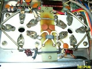
In this photo, IW1PUR has tied the three grid pins together nicely but they are NOT hard grounded. Each tube is only grounded via the silver mica caps at the bottom. This is NOT what you want.
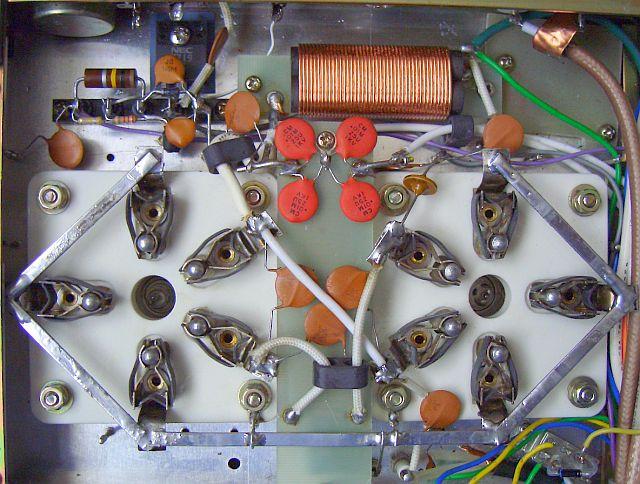
This next photo by PA0FRI has the 3 grids pins on each tube all tied together and it looks really neat. The hard grounding is using the bottom inside socket bolt on each socket, and one chassis ground, right of centre. This is better by a long shot but I think you could do much better.
Elsewhere on PA0FRI’s web site he states. “A few years after the first modifications I considered that in the tube 3 external grid connections (2,3,4) are bolted to the same point. In nature, is a law of the least energy and therefore electricity follows the shortest path. You can disagree if you like, but I doubt that current flow simultaneously along 3 separate grid connections. So paralleling the external pins is for HF unnecessary. Just by grounding one pin the current is forced to flow via one point and that improves the HF stability of a tube is my opinion. Therefore, all components soldered at the pins were removed and one per tube was grounded.”
This logic might be true at DC or mains frequency, but we are dealing with high frequency RF. I don’t think this is good advice, and I am compelled to disagree. Frits Geerligs post clearly expected such a response when he mentioned “you can disagree if you like”.
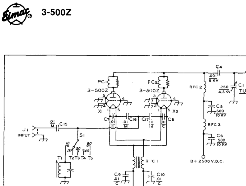
You might find this next image of interest. This is an Eimac document. Note how they detail that the single grid, has 3 pins, (2,3,4) and they show each of the 3 pins grounded individually. They don’t join them together and then provide just a single ground. You don’t often see that extra detail shown on a circuit diagram, but Eimac did. That sort of tells us something right?
Good RF design will always come back to these simple basics. Keep RF paths as short as possible. Really short is always better. So a physically short path to ground is optimum. As frequency rises, a length of wire starts to look and act like an inductor. We don’t want that. As RF travels on the skin of the conductor, then the use of wider flatter conductors is great. Remember we are not worried about the DC component. Think in terms of RF.
HL3AMO used braid and tied them all together and hard grounded each with its own chassis ground. These chassis ground pins are standard in these locations if I remember correctly.
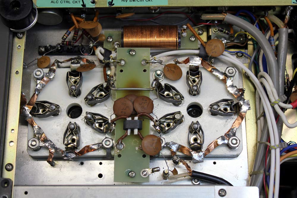
TK5EP Also tied the 3 grid pins to hard ground by using the outside pair of socket bolts on each socket. I can’t be certain if he relied entirely on the socket bolt grounding or added extra paths to chassis ground that I can’t see in the photo. The LH socket might be tied to a lug at the bottom of the photo. I am not sure about the RH tube socket ground point, other than the socket bolts.
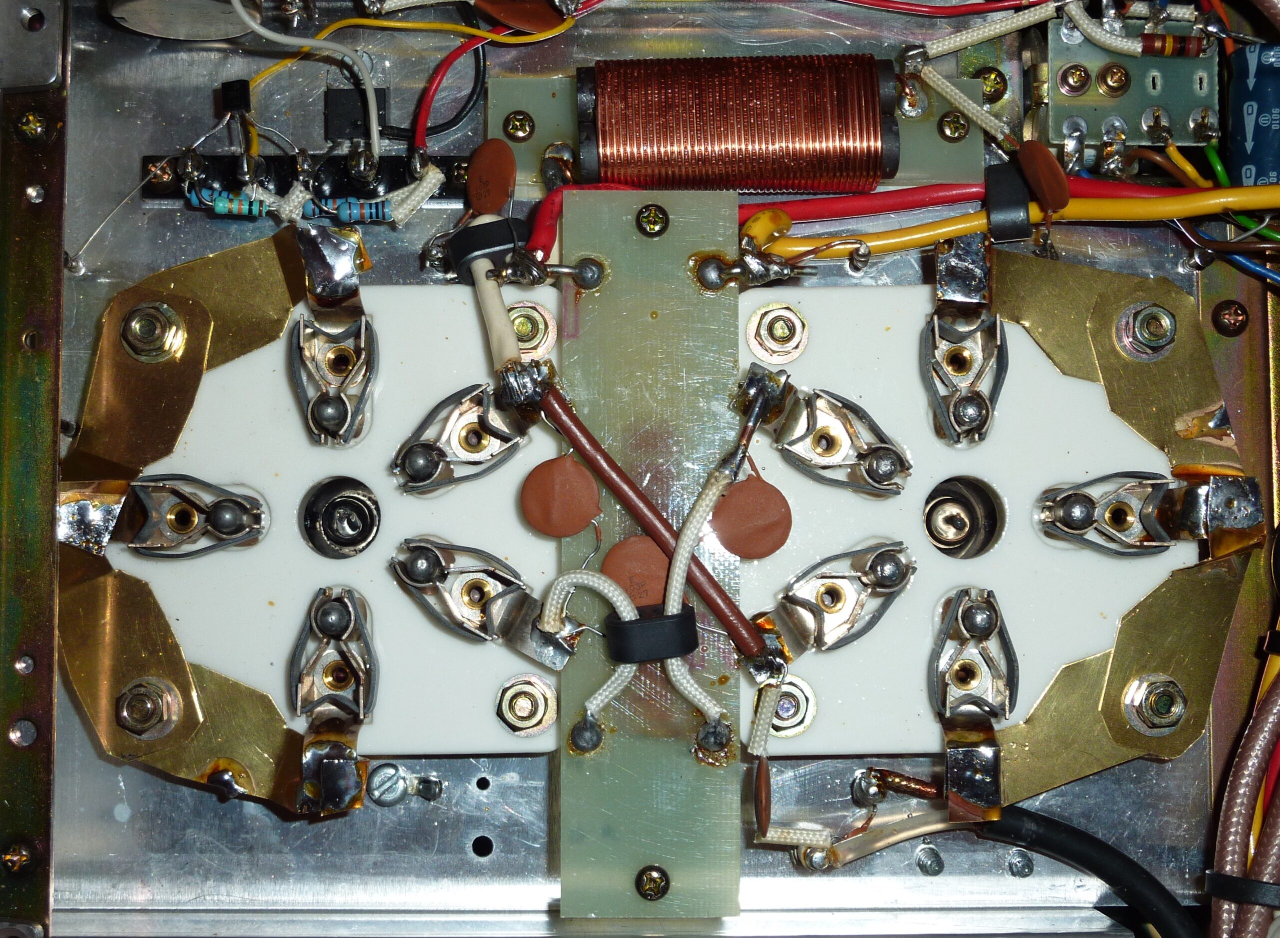
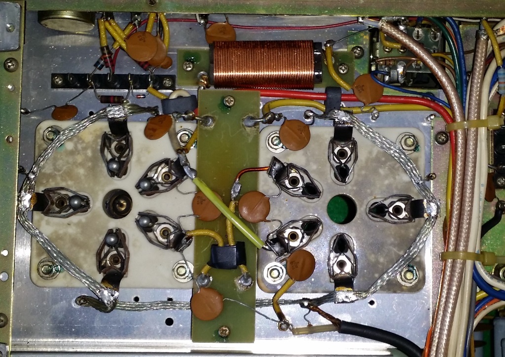
W8JI used copper strap to tie three pins together and obtained hard grounding by using 3 of the socket bolts on each socket, as well as 3 chassis ground points at each socket, near the tube pins.
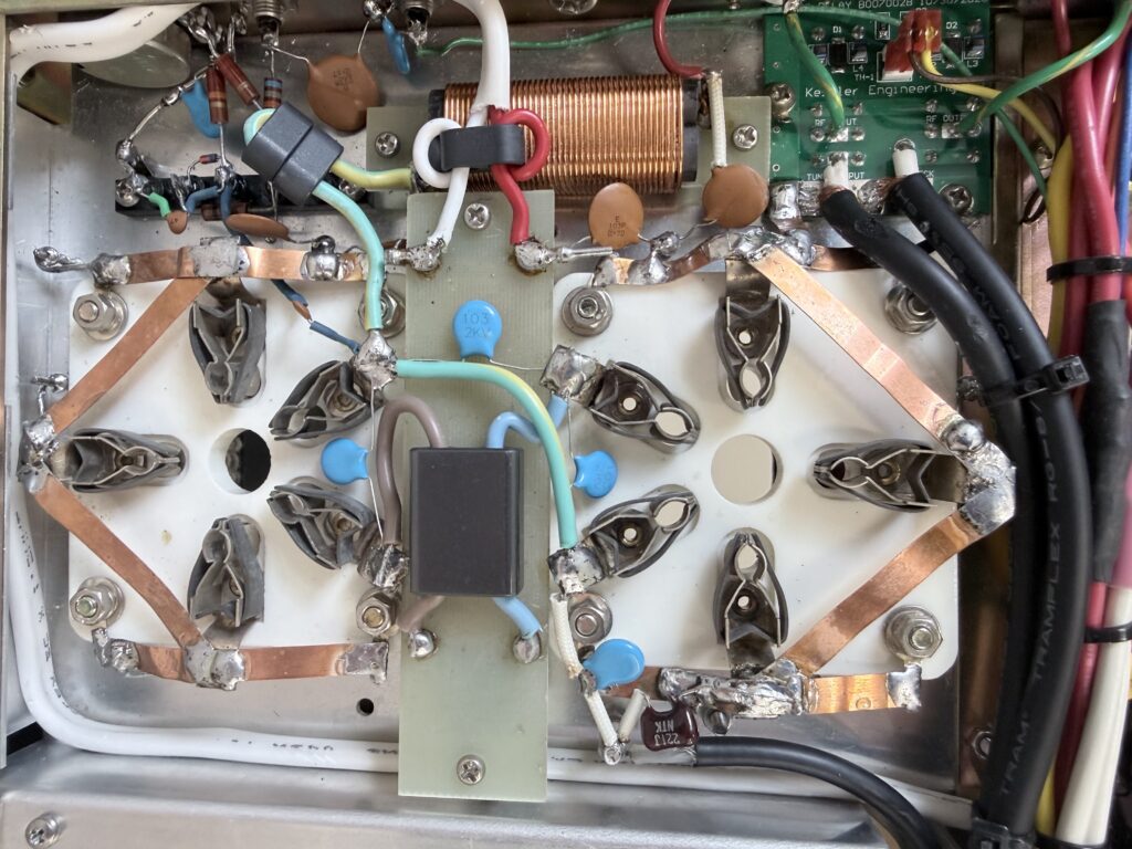
This is what I did in my amplifier. I know it may not be the neatest, but each tube socket uses a solder lug under the 4 socket bolts, and in addition uses four chassis grounds locations nearby. I have the confidence that the grids are grounded to the best of my ability and this will maximise stability.
I also did some other mods for stability under the page “RF Return”. Please consider these as necessary or highly recommended improvements.
Extra RF FixesImage credits: qro.it and others as mentioned in the text.