Parasitic Suppressors
This subject became a super hot potato over 25 years ago after QST published articles written by Richard Measures, AG6K (SK). Richard promoted the idea that if we lowered the Q in the parasitic suppressor by using NiCh wire as the inductor, instead of using a flat larger surface area conductor like copper strap, then it would help control VHF parasitic oscillations. He felt so strongly about the use of NiCh, he stated “Someday, you may be able to buy amateur radio amplifiers that use low VHF-Q parasitic-suppressors”, and then added that until that day we will have to fit them ourselves. This quote is from the opening paragraph of “Constructing and Retrofitting Low VHF-Q Parasitic Suppressors.”
When QST published some of his articles it added a high degree of credence to what he claimed. Richard had a way with words and his presentation sounded logical. October 88 issue “Improved Anode Circuit Parasitic Suppression for Modern Amplifier Tubes”. And later in 1990 a 2 part follow-up article, “Parasitics Revisited” in the September and October editions. This is what likely started a true cult following when it came to parasitic suppressors and the use of NiCh.
I was sucked in by what I read and purchased a bunch of kits. Parasitic kits for the TL-922 as well as a 4-1000A amp I was building, A QSK kit and vacuum relays, filament voltage reduction kit. I just went for it. The QSK kit was pretty good but later I did swap it out. In my case, all NiCh has since been removed from the amplifier. Why?
In the intervening 25 plus years that have passed I have continued to learn, and with the luxury of hindsight I now am able to review the articles and re-evaluate the best way forward. Not being an Engineer or an RF guru, I might well be proved wrong in some of the points I present but if you think I am wrong, please send me a note on the contact page.
Looking back in review, I personally feel that NiCh promotion has come up short on actual test results. No scans, no measurements, oscilloscope results, no Smith charts, although I find Smith charts hard to understand, (so much more to learn, right?) There was no way of isolating that claimed improvements were correctly attributed to the changed suppressors.
Other modifications like replacing the antenna change over relays and fixing sequencing undeniably stop excessive tank circuit voltages, and with it, the arching, on band switches and the Plate and Loading capacitors. I strongly suspect that so often parasitics were blamed for these issues.
The kits I purchased had me departing from good RF design technique.
In the article “Constructing and Retrofitting Low VHF-Q Parasitic Suppressors” on page 2, item 2 it says, “At the anode-circuit only, where practical remove any copper or silver straps, braid or heavy buswires, that exceed 0.8 inch in length”.
He is referencing the HV wiring after the main RFC (L1) and the main coupling capacitor to the Tank Circuit (C34). As RF travels on the skin of the conductor, we are being advised to remove all the items with skin in the game and replace it with very thin NiCh 60 leads and inductors, that are anorexic at best.
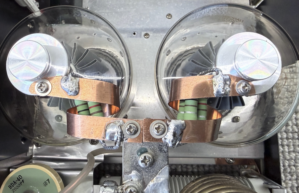
And the one on the right? In the kit he describes it this way, “This unconventional looking suppressor is made from a straight Ni-Ch wire in parallel with a 2nd NiCh that has a 1 turn ¼ inch ID coil at its mid point”
Think about it. Those NiCh suppressors have almost no surface area to speak of. That’s like changing a 6 lane freeway down to a single lane and expecting this to work wonders.
The NiCh parasites continued to evolve and are the now common U shaped hairpins. They used NiCh with 2 non-inductive resistors across the open end of the hairpin. They certainly are a bit prettier.
As a side point that no-one seems to take much notice of, Richard said on page 5 of his “Constructing and Retrofitting Low VHF-Q Parasitic Suppressors”, at the bottom of paragraph 1, starting in bold type. “However, for multi-tube amplifiers, U inductors are difficult to decouple from each other.” Richard then had a drawing where the U (hairpin suppressor) is for single tube amplifiers. For multi-tube amps he recommended the ones he sold me. See the first photo.
Today no-one seems to pay any attention to Richard’s concerns about the coupling issues with two tubes. Who knows you can see pictures online of all manner of variations and alignment. Most are in the same plane and some, having one at 90 degrees to the other. Perhaps that is deemed to decouple them.
Today on ebay, many are selling this cult parasitic suppressor layout. Often without the use of NiCh at all. So much for low Q. These non-NiCh suppressors are simply U shaped inductors made from less surface area materials, in many cases, and are certainly easier to fabricate than a wound inductor.
Simplistically, we don’t want the suppressor to affect the amplifiers performance on the HF bands. At the same time we don’t want the amplifier to take off and oscillate at some VHF parasitic. The suppressor needs to stop that oscillation.
What has helped me, is the detailed analysis of W8JI. Tom explains what is happening and how the process works. His subject is Parasitic Suppression at VHF frequencies.
If a TL-922 is going to take off, it will be at VHF. Something between 130-190 MHz. His article is not TL-922 specific as such, but it will apply to the TL-922. https://www.w8ji.com/vhf_stability.htm
He even did a write up of how to fabricate a suppressor, and tune it by a sequence of tests. https://www.w8ji.com/testing_for_stability.htm. I have saved this as a pdf file on my computer so I can reference it at any time when needed.
When we purchase a discrete component we are clearly told the values and ratings of the device be it R, C, L transistor, diode, tube, pick any component. We can’t say the same thing about a parasitic suppressors due to the wide frequency coverage and that is also affected by interactions of where it is placed. But the following gets me a lot closer than ever before. It is taken from Toms article at https://www.w8ji.com/vhf_stability.htm
Imagine: We have a tube (3-500 for example) and a suppressor will be put under test. Tom graphs the current in the inductor as a green trace, and likewise the current in the resistor as a red trace. The screen will display frequency on the horizontal axis, to 300 MHz. The measurements start at 30 MHz through to 300 MHz. ie. We are looking at the VHF frequency range where a 3-500 might oscillate. Tom then comments on the data shown. His explanation follows in blue highlighted text.

Starting at 30MHz, the ratio of current in the inductor to current in the resistor is:
Frequency -I(L1) -I(R1)
30MHz 0.0047 0.0015
60 0.0041 0.0026
90 0.0034 0.0034
120 0.0029 0.0037
160 0.0024 0.0041
190 0.0021 0.0042
220 0.0018 0.0043
This tells us something very important. The INDUCTOR dominates only at low frequencies. At 30MHz, current in the inductor is three times current in the resistor.
At 190MHz, in the range of the instability frequency of a 3-500Z, the resistor has twice the current as the inductor.
This tells us any changes in INDUCTOR design or inductor Q (such as use of nichrome wire) mainly lowers low frequency Q. It would have virtually no effect on very high frequency Q of the system.
- The dominant factor in controlling VHF Q is the resistor value, and any reactance in the resistor path
- The dominate factor in determining HF Q and performance is the inductor value, and any changes in inductor Q
This has been my point all along with the Measure’s nichrome suppressor. Measures claims, incorrectly, his suppressors provide lower VHF Q while, in fact, they do exactly the opposite! A typical Measures hairpin suppressor actually produced significantly higher system Q in the anode of a 3-500Z (nearly twice the VHF Q), because the equivalent Rp of the suppressor in series with the anode lead was lower!
This put real numbers to performance, and I could understand the principle. If you read on further in his article … he explains it is possible to shape the curve by adding a capacitor in series with the resistor. A very interesting article. Please check it out.
I have removed everything out of the amp that I had purchased from Richard AG6K because, on two occasions now, I ended up with advise and implementation that did NOT do what it was claimed to do.
Firstly, regarding the 3-500 filaments, the NiCh leads in the filament supply was the worst thing I could have done. It was damaging.
Secondly, the NiCh suppressors did exactly the opposite of what they were claimed to do. Specifically claiming to lower VHF Q while actually increasing the VHF Q.
A third reason: It appears to me, that the story changes in ways that don’t add up. So staying with the article “Constructing and Retrofitting Low VHF-Q Parasitic Suppressors” Page 5 makes the comment “Since catching a parasite in the act is virtually impossible with ham type test gear …” yet earlier on page 3 he wrote
“Here’s how to tell whether arching is VHF parasitic or HF fundamental in nature. If you have installed the glitch protection components of the retrofit kit”. “switch the meter to measure Ig. If VHF energy (ie. a parasitic) is causing the arcing, Ig will increase during the arc. If the arcing is caused by HF energy, Ig typically decreases during the arc.”
Isn’t this a contradiction? One second it’s too short lived to catch. The next moment, you can identify it while in the act. One minute, you can’t test with ham gear, but then the next you can with the amp monitoring grid current after installing his kit.
There is no way on earth that I would allow an arc to continue to burn in my amp so I can monitor grid current. We all know what an arc welder does to the metals at the point of the arc. I don’t fancy sacrificing aluminium plates in the variables or the band switch contacts, just to monitor which way the grid current is tracking. I no longer trust the advice.
I have not re-installed the original suppressors. I thought I would have a go at making my own. Obviously getting good non-inductive resisters is essential. I chose Ohmite resistors. The OY series are the 2 watt rated. Not only are they non-inductive, they are rated to 220 degrees C, so are in the same league as the maximum seal temps on the tubes. The pulse and overload capabilities look very good as well.
I used three resisters in parallel for each suppressor. I only had in my stock, five 100R and five 120R. I would need 6 for the 2 suppressors. So I settled on using two 100R and one 120R in parallel for each suppressor. A nominal 35 ohms at 6 watts. I spaced the resisters apart so that air was able to move freely around each unit.
For the inductor I had some copper strip that had a thickness of 3mm and a width of 10mm. I formed it into a single turn with a 25mm coil diameter.

Not yet installed just checking alignment etc.
Others came up with this configuration first. N5CNN has an almost identical suppressor in his QRO HF2000 amp. Longer lengths but a single turn and 33 ohms.
JH2CLV in his TL-922 had to change the parasitic suppressors when he added 6m. At 52 MHz the standard suppressors went to ash.
I have copied JH2CLV and N5CNN suppressors and will apply it to mine.
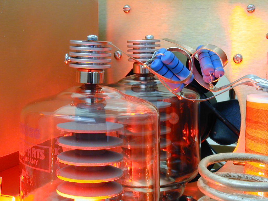
Image credits: VK3BBQ, ebay.com, W8JI, N5CNN, and JH2CLV