Power Switch
In-rush current on switch on, was very high. Over 40 amps. All the lights in the home would dim. After some time it was known that the power switch contacts could weld themselves together. Not good. However, to this day people can still buy new replacement switches from Harbach Electronics. https://harbachelectronics.com/product-category/kenwood-tl-922 In my case I wanted to solve the issue prior to switch failure and chose to install a soft start.
At first I mounted a small relay and a home brew control circuit copying someones design (sorry I can’t remember who’s design it was, it was over 20 years ago) but I installed it in the same general area where the terminal blocks for setting the supply voltage lived under the fan cover. Recently, I have ripped out my old home brew setup and replaced it with kit that includes many other modifications from Kessler Engineering. This page is just focusing on the soft start to save having to replace the power switch. To see all the elements covered in the kit from Kessler Engineering, look under the “More Mods” pull down, and then drop down the list to “Kessler Eng Kit.”
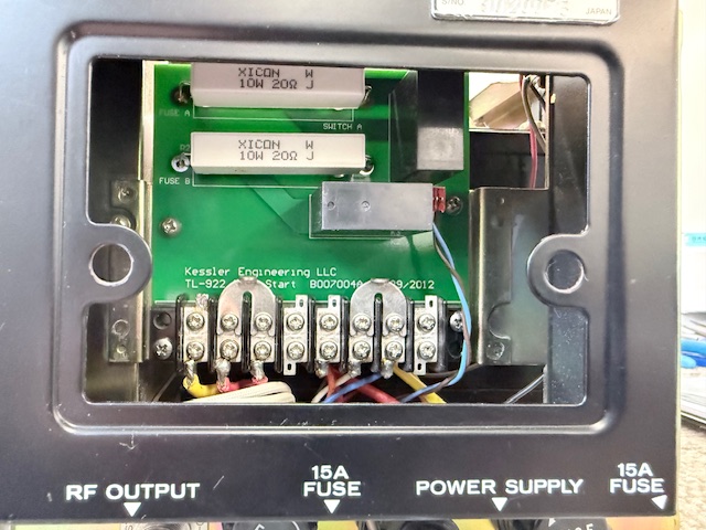
The original mains fuses remain. Each mains cable has its own 20 ohm 10 watt resistor and a relay to bypass the resistor after the delay. So it has 40 ohms in-circuit initially to accomplish the soft power-up. The photo shows it housed in the rear fan enclosure. I had removed the upper terminal strip and the new PCB installs using the original screws. The 12 volt relays are double pole relays, but both poles are in parallel to handle higher current. So one relay is handling the active and the other the neutral.
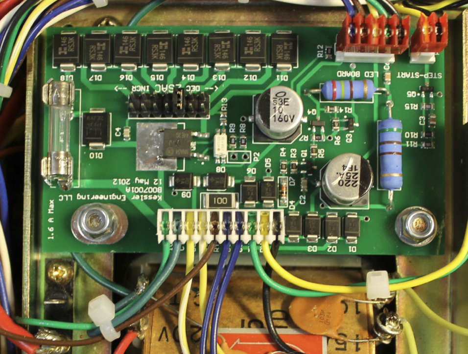
The control for this step start is on the main control PCB. The 2 pin header on the top RH corner of the picture is the cable that runs down to the step-start relay board housed under the fan cover.
Step Start Circuit: The 12 volt supply is obtained by taking the 8 volt AC winding on the filament transformer (originally ran the meter lamps) and using a bridge and 220 uf cap on the control board. The Step-Start is as below. I am not sure what the time delay is. It is fairly short. It certainly stops the house lights from dimming and definitely will protect the power switch. I also hope that the delay is long enough to help with the filament inrush. Eimac recommended that for best tube life, we should limit filament in-rush current to twice normal current. In the 3-500’s, “Normal” is specified as between 13.8 and 15 amps. So the highest level of filament inrush should be limited to 30 amps. Fingers crossed. Sorry but I don’t have the gear to check this.
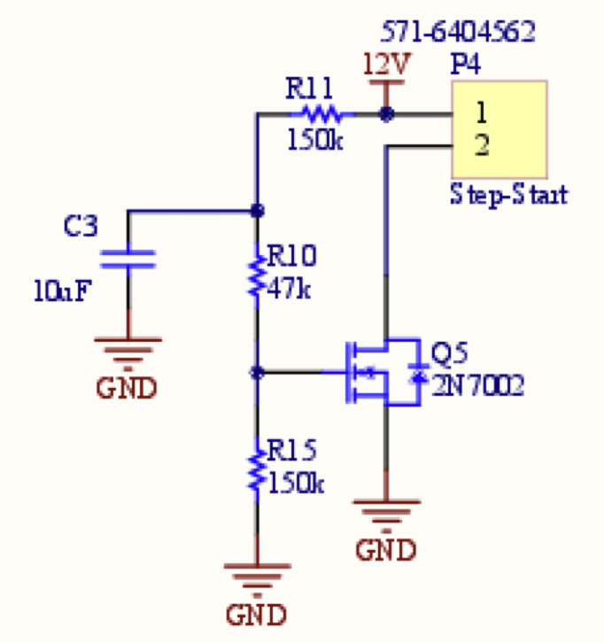
Image credits: VK3BBQ and Kessler Engineering